 learndesign
Arranging parts for the laser with Fusion Arrange
Modify → Arrange packs every flat part of your model onto a 600 × 300 mm sheet in one go. Set the envelope, pick the components, read the result, then project the layout to a sketch and save it as a DXF.
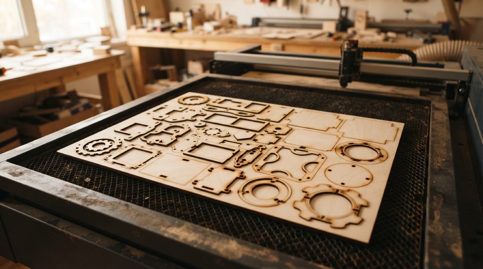
Every laser project ends the same way: a pile of flat parts that have to fit on one sheet without overlapping and without wasting half the plywood. Dragging them around by hand works for three parts. For thirty, use Arrange. It takes the components in your design, finds a layout inside a boundary you give it, and leaves the original assembly alone.
Arrange is in the paid and education licences of Fusion. It is not in the free personal licence.
Before you start
- Every part has to be a component, not a loose body. Select the bodies, right-click, Create Components from Bodies.
- Each part should be a flat plate the thickness of the sheet (2.8 mm plywood, modelled at 3 mm). Arrange lays components on their largest flat face, so a part with a feature sticking up will not sit flat.
- Know your sheet. The laser bed is 600 × 300 mm. Offcuts are smaller; measure them.
Run Arrange
Modify → Arrange. The dialog has two tabs.
- Envelope. Pick a plane, a face or a sketch to lay the parts on. The bottom origin plane is the usual choice. Type the length and width of your sheet, 600 × 300 mm for a full sheet. For an odd-shaped offcut, draw its outline as a sketch and pick that instead.
- Objects. Drag a box around every component, or click them one by one. Set a quantity if you need more than one of a part; you do not have to copy it first.
- Create Copies on. Arrange then places copies and leaves your assembled model where it was. With it off, it moves the originals.
- Arrange type: 2D True Shape nests parts by their real outlines and uses the least material. 2D Rectangular treats each part as its bounding box. It wastes more sheet but gives tidy rows, which is easier when you are cutting part of a sheet now and the rest later.
- Object spacing 1 to 2 mm. The kerf is about 0.1 mm, but a gap keeps two outlines from being cut twice along a shared edge and leaves a bridge so small parts do not drop and shift mid-cut. Frame width 3 to 5 mm keeps parts off the sheet edge, which is rarely square.
- Allow rotation on, unless you need the grain running one way, in which case limit it to 180°.
- Leave Allow partial arrange off. Then Fusion warns you when something did not fit instead of quietly leaving it out.
Click OK. The layout appears in an Arrangements folder in the browser. Open it, hide the original components, and look at the sheet from above. If a part is in a silly place you can still drag it in the arrangement.
Get it to the laser
- New sketch on the envelope plane.
- Create → Project, select every arranged body, and turn projection link on so a later change to a part flows into this sketch.
- Finish the sketch. Right-click it in the browser, Save as DXF.
- Open the DXF in the laser software and measure one known dimension. If it is right, the whole sheet is right.
Engraved details (labels, part numbers) go in the same sketch as closed profiles or text, in a different colour, so the laser treats them as a separate job.
Related
- Slicing and lamination uses Arrange on a stack of twenty-odd layers.
- Kerf, explained covers the 0.1 mm the laser takes and why slots are modelled at 3 mm.