 learndesign
Designing for FDM
The numbers that make a part print well on a filament printer. Tolerances for fits, the overhang rule, minimum feature sizes, and how nozzle size sets both the layer height you can use and the smallest detail you can make.
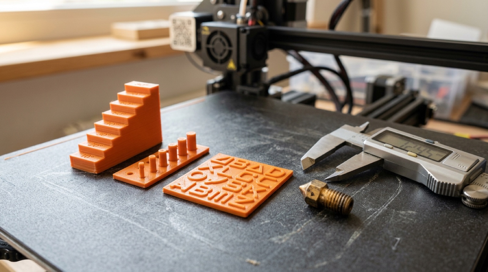
A filament printer draws a part one bead of plastic at a time. Every rule below comes from that. The bead has a width, set mostly by the nozzle. It has a height, the layer. It is soft when it lands and needs something under it. And it shrinks a little as it cools. Design with those four facts in mind and most prints work the first time.
Numbers here are for a 0.4 mm nozzle on a well-tuned printer in PLA or PETG, unless it says otherwise. Your printer will differ a little; test a fit or an overhang once on your own machine, write the numbers on it, and use those.
Tolerance and fit
CAD is exact. Prints are not. Holes come out smaller than drawn, outside dimensions come out a little larger, and the first layer squishes outward. Plan for it.
| Fit | Clearance to add (per side) | Feels like |
|---|---|---|
| Press fit, permanent | 0.0 to 0.1 mm | Needs a mallet or a vice |
| Snug, hand press | 0.1 to 0.2 mm | Firm push, holds itself |
| Sliding, moving part | 0.25 to 0.4 mm | Slides freely, no rattle |
| Loose, drop-in | 0.5 mm | Bolt through a hole |
- Holes shrink. A 5 mm hole prints at about 4.7 to 4.8 mm. Either draw it oversize, or draw it exact and drill it out; drilling gives a better hole anyway. Vertical holes (axis along Z) are round; horizontal holes come out slightly oval and sag at the top.
- Elephant’s foot. The first layer is squashed wider by up to 0.3 mm. Put a 0.4 to 0.5 mm chamfer on every edge that touches the bed, and the part will sit flat and fit its neighbour.
- Make clearance a parameter. One number, referenced by every mating dimension. Print a 10 mm coupon of the interface, adjust, reprint. Two coupons usually get you there; a full part that does not fit teaches you less and costs an hour.
- Layers add friction. Parts that slide along Z rub on the layer ridges. Give them more clearance, or orient the sliding surface in XY.
Overhangs and bridges
Plastic has to land on something. Each layer can stick out a little past the one below, and the limit is about 45° from vertical. Steeper than that and the bead droops, curls, and leaves a rough underside. Steeper still and it fails.
- Under 45°: fine. Chamfers, slopes, and cones all print cleanly.
- 45° to 60°: rough. Prints, but the underside looks bad. Acceptable where nobody sees it.
- Over 60°: supports or redesign. Supports cost time, material, and a scarred surface where they touch. Redesign first.
- Bridges are a different case. A flat span between two supported ends can print unsupported up to about 20 to 30 mm because the bead is pulled tight. Longer than that and it sags.
- Horizontal holes have a ceiling that is a small overhang. Above about 8 mm the top sags and the hole is no longer round. Use a teardrop: a hole with a pointed top at 45°, so every layer is supported.
Ways to remove an overhang without supports: add a 45° chamfer under it, split the part and print it in two pieces on their flat faces, turn a horizontal hole into a teardrop or a hexagon, or rotate the whole part so the overhang becomes a wall.
Minimum feature size
Everything is built from beads about 0.4 to 0.45 mm wide. Features smaller than one bead do not exist to the slicer, and features of one bead are fragile.
| Feature | Minimum on a 0.4 nozzle | Comfortable |
|---|---|---|
| Wall, cosmetic | 0.45 mm (one bead) | 0.8 mm (two beads) |
| Wall, structural | 0.8 mm | 1.2 to 1.6 mm |
| Pin or post, unloaded | 2 mm diameter | 3 mm |
| Pin, loaded or snapped in | 4 mm | 5 mm and up |
| Embossed text or logo | 0.5 mm high, 0.8 mm stroke | 1 mm high, 1.2 mm stroke |
| Engraved text | 0.4 mm deep, 0.8 mm stroke | 0.6 mm deep, 1 mm stroke |
| Slot | 0.5 mm wide | 1 mm |
| Vertical hole | 1.5 mm | 2 mm and up |
| Living hinge | 0.4 mm thick, one layer wide | 0.6 mm, PETG or PP |
Two rules make the table make sense. Walls should be whole multiples of the bead width: 0.8, 1.2, 1.6 mm. A 1.0 mm wall is two beads with a gap, or one bead and a slicer guessing; either way it is weak. And inside corners come out rounded by the nozzle radius, so a sharp internal corner in CAD is a 0.2 mm radius in plastic. If something has to fit into that corner, relieve it.
Threads: model them only at M8 or larger, and expect them to strip under load. For anything smaller or anything structural, use a captured nut, a bolt through to a nut, or a heat-set insert.
Strength has a direction
The bond between layers is the weakest part of the print. A part pulled apart along Z, or bent so a layer line is on the tension side, fails at a fraction of the strength it has in XY. Orient so layers run across the load, not along the line the part would snap. If the part has to be strong in two directions, print it as two pieces or add a fillet where the crack would start; a fillet spreads the stress across more layers.
Layer height and nozzle size
The layer height you can use depends on the nozzle. A layer thinner than about a quarter of the nozzle diameter over-squishes and the flow gets unreliable; thicker than about three quarters and the bead does not bond to the layer below.
| Nozzle | Usable layer height | Typical | What it is for |
|---|---|---|---|
| 0.25 mm | 0.06 to 0.18 mm | 0.12 | Miniatures, fine text, small threads |
| 0.4 mm | 0.10 to 0.30 mm | 0.20 | Everything, the default |
| 0.6 mm | 0.15 to 0.45 mm | 0.30 | Functional parts, faster, stronger walls |
| 0.8 mm | 0.20 to 0.60 mm | 0.40 | Big parts, vases, props |
Layer height is vertical resolution. It sets how smooth a slope or a curve looks from the side, how visible the stair-steps are on a shallow dome, and how long the print takes: halving the layer height doubles the time. It does not change the smallest detail you can draw in plan view. That is the nozzle’s job.
Thicker layers also bond better, because there is more hot plastic per layer and it stays hot longer. A 0.6 nozzle at 0.3 mm layers prints a stronger bracket than a 0.4 at 0.12 mm, and in a third of the time. Save fine layers for parts that need to look smooth.
Horizontal resolution and nozzle size
In plan view, the smallest thing a printer can make is one bead, and the bead is roughly the nozzle diameter. Slicers set extrusion width between the nozzle size and about 1.2 times it, so a 0.4 nozzle lays a bead 0.4 to 0.48 mm wide, a 0.6 nozzle a bead 0.6 to 0.7 mm wide.
That single number decides:
- Minimum wall. One bead. Practical minimum, two beads: 0.8 mm on a 0.4, 1.2 mm on a 0.6.
- Smallest text and detail. Strokes need to be at least two beads to have a wall on each side. On a 0.6 nozzle, 1 mm text turns to mush; on a 0.25, it is crisp.
- Inside corner radius. Half the bead width, always. Sharp inside corners do not exist.
- Gap filling. A feature that is 1.5 beads wide leaves the slicer a choice: leave a gap, or over-extrude. Both look bad. Design widths in bead multiples and the problem goes away.
- Speed. A 0.6 nozzle moves about 2.25 times the plastic of a 0.4 per pass, so walls and infill go down much faster.
So the two resolutions are separate. Nozzle diameter sets XY detail and the minimum wall. Layer height sets Z detail and surface smoothness, within a range the nozzle allows. You cannot get fine text out of a big nozzle by using thin layers, and you cannot get a smooth dome out of thick layers by using a small nozzle. Pick the nozzle for the finest plan-view feature the part needs, then pick the thickest layer that gives an acceptable surface.