 learndesign
CAD practice: a functional part from a drawing
Model a flanged bushing from its technical drawing in Fusion: two extrudes and a fillet. The weight on the drawing tells you if you got it right.
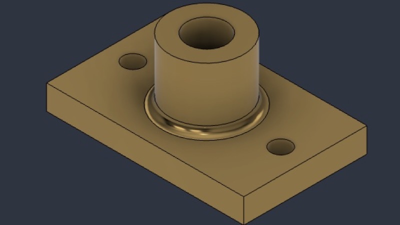
This is a flanged bushing. The plate bolts down through the two small holes, and a rod or shaft runs through the bore in the middle. It is about as simple as a real part gets, which makes it good practice for the thing that matters here: reading a technical drawing and turning it into a model that matches it exactly.
It takes two extrudes and one fillet. The drawing gives you every dimension, and its title block gives you the weight of the finished part. Your model is done when Fusion reports the same weight.
The drawing
Read it before you touch Fusion. The top view on the left gives the plate outline and the three holes. The side view in the middle gives the heights and the R3 fillet where the boss meets the plate. The 25 and 40 locate the centre of the part from the plate’s edges, so the centre sits dead in the middle of an 80 × 50 plate. Ø means diameter and R means radius. The 70 runs from the left edge to the right bolt hole, which puts the two bolt holes 60 mm apart, 30 mm each side of centre.
Extrude 1: the plate
- New design. Check the units are millimetres (Browser → Document Settings).
- Sketch on the ground plane. Centre rectangle from the origin, 80 × 50.
- Circle at the origin, Ø16. This is the bottom of the bore.
- Two circles Ø8, one each side, on the horizontal line through the origin, 30 mm from centre. Draw one, dimension it, then use an Equal constraint on the second so you only type the size once.
- When the sketch lines all turn black, it is fully constrained. Finish the sketch.
- Extrude 10 mm, New Body. Click inside the rectangle but not inside the holes, so the holes stay open.
Extrude 2: the boss
- New sketch on the top face of the plate.
- Circle Ø30 centred on the hole in the middle (hover the hole edge and snap to its centre). Then a Ø16 circle on the same centre.
- Extrude the ring between the two circles 25 mm, operation Join. Plate plus boss is 10 + 25 = 35, the overall height on the drawing.
Drawing Ø16 in both sketches is what makes the bore run all the way through. You could extrude a solid Ø30 cylinder and cut the hole afterwards, but that is an extra feature for the same result.
The fillet
Fillet (press F) the edge where the boss meets the plate, 3 mm. A fillet at an inside corner like this removes a sharp corner where stress would concentrate, and it adds a small amount of material, enough to show up in the weight.
Check the weight
Expand Bodies in the browser, right-click the body and check Physical Material. It should be Steel, which is Fusion’s default. Then right-click the body and choose Properties. Mass should read 391.08 g (0.391 kg if it shows kilograms).
If it doesn’t match, the difference tells you where to look:
| Mass | What’s probably wrong |
|---|---|
| 389.59 g | The R3 fillet is missing |
| about 406.9 g | The Ø16 hole is missing from the plate sketch, so the bore is blocked at the bottom |
| about 430.5 g | The boss is a solid Ø30 cylinder with no bore |
| way off | Wrong material, or the units were inches when you typed the numbers |
The reference model
Orbit it, section it, or use the measure tool in the viewer to compare with your own. Try the drawing first, though. Measuring the answer teaches you less than reading the drawing does.