 learndesign
Functional 3D printing
Find something around you that is broken, missing a part, or annoying to use, and fix it with a printed part. The part has to work, and it has to be designed for the printer, not just printable.
Overview
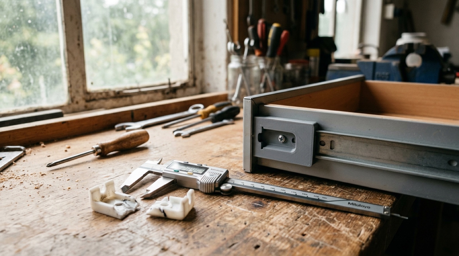
Most broken things are broken by one small plastic part. A clip, a knob, a bracket, a foot, a cap, a hinge pin, a battery door. The rest of the product is fine and gets thrown out anyway. A 3D printer, some calipers and an hour in Fusion can put it back in service. That is the point of this project: a real fix or a real improvement, not a demo.
The part you make has to do two things. It has to work on the product: fit, hold, survive. And it has to be a good print: the right orientation for the load, no unnecessary supports, walls the printer can actually make, and a print time and material use you can justify. A part that needs three hours and a raft of support to replace a clip that snapped is not well designed for additive, even if it fits.
Fix, repair or improve. Fix means it does the job again. Repair means it does the job again and lasts. Improve means the product works better than it did before, because you noticed something the original designer did not. All three count.
Skills needed
- Measuring for a fitCalipers on the mating part, not the broken one. Inside, outside and depth, and where the load goes.
- Modelling from measurements in FusionReference geometry first, part second. Parameters for every dimension that came from a caliper.
- Designing for additiveOrientation for strength, 45° overhang rule, wall thickness in nozzle multiples, chamfers at the bed, teardrop holes, no supports where you can avoid them.
- Slicing and reading the estimateLayer height, walls, infill, and what each one does to time, material and strength. The slicer estimate is a design number.
- Testing a fitted partFit, then load, then use it for a week. Print v2 from what you learned.
Assessment
| Criterion | Developing | Proficient | Exemplary |
|---|---|---|---|
| Problem and measurement | Vague problem, few numbers | Clear problem, all mating dimensions measured and recorded | Measured the load path and the failure of the original, and designed against it |
| CAD | Numbers typed in, hard to change | Parametric, fits after one coupon | Refits a similar product by changing parameters; original part’s weakness is fixed |
| Design for additive | Supports everywhere, thin walls, wrong orientation | Oriented for strength, self-supporting, walls in nozzle multiples | Under time and material budget with margin; chamfers, teardrops and bridges used on purpose |
| Function | Fits but loose or fragile | Fits, holds, survives the load test | Survives a week of use; better than the original |
| Test record and v2 | None | Fit, load and use recorded | v2 printed from evidence and measurably better |
Deliverables
- A problem card with a photo of the product, what is wrong, who it affects, and the measurements you took
- The Fusion file with parameters, and the STL
- A slicer screenshot showing orientation, supports (or none), print time and material used
- The part, installed on the product, before-and-after photos
- A test record covering fit, load and a week of use, plus the v2 change if there was one
Materials
- A product to fix, from home or from a box of broken things
- PLA for prototypes, PETG or ASA for parts that see heat, sun or repeated load
- Calipers, a profile gauge, and a marker
- Small hardware if the design calls for it: M3 screws, heat-set inserts, a spring
Steps
Week 1: Find it, measure it, design it
- Find the thing. Bring it in. If you have nothing, start a box of broken products and pick one whose problem you can name in one sentence.
- Write the problem card. What broke or what is annoying, who uses it, what the part has to do, and what it must survive: a pull, a twist, a drop, sunlight, the dishwasher.
- Measure the mating parts, not the broken piece. The broken piece is a hint; the thing it fits into is the truth. Record every number. Photograph with a ruler in frame.
- In Fusion, create parameters from your measurements and model the mating geometry as a reference body. Then model your part around it. Add a clearance parameter, starting at 0.2 mm.
- Before you finish the model, decide the print orientation and design for it. Chamfer the edges that touch the bed. Turn horizontal holes into teardrops. Replace steep overhangs with 45° slopes. Thicken walls to nozzle multiples.
Week 2: Coupon, print, fit
- Print a coupon: just the interface, 5 to 10 mm tall. Fit it. Adjust the clearance parameter. Reprint until it fits by hand, snug but not forced.
- Slice the full part. Read the estimate. If it is over 2 hours or 40 g, change the design: hollow it, thin it, shell it, or reorient it. Screenshot the slicer when you are under.
- Print in the final material. PETG or ASA for anything that sees heat, sun or repeated load.
- Fit it to the product. Photograph before and after.
Week 3: Test, use, revise
- Load test: do to it what the user does, ten times, harder than they would. Then leave it in use for a week.
- Record what happened. Loose, tight, cracked, worn, fine.
- If anything failed or annoyed, change the model, reprint, and record v2. If nothing did, write down why you think it held and what you would change for a version that had to last five years.
- Finish the test record and hand in the product with the part installed.
Stretch options
- Make it a family: change the parameters and print the same part for two more products.
- Multi-material: a TPU pad or grip on a rigid body.
- Design the part so that when it fails, it fails somewhere cheap and replaceable instead of in the product.