learndesign
Laser-cut phone stand
A one-lesson project. Model a two-piece slot-together stand in Fusion and cut it from 3 mm plywood so the slots hold without glue.

Overview
Design and cut a phone stand made from two flat pieces that slot together at right angles. The whole thing has to come out of a single 200 × 150 mm offcut, hold a phone at a usable angle for watching a video, and stay together without glue. It is a small project, but it forces the two ideas that matter most on the laser: drawing a sound slot joint, and compensating for kerf.
Skills needed
- Plane, sketch, extrude in Fusion↗
- Sketching and constraints in Fusion↗
- Designing slots for kerf
- Laser cutter setup and safety
Assessment
Assessed in the lesson, by looking at the finished stand:
- Fit. The slots hold with friction. No glue, no wobble, no forcing with a mallet.
- Function. A phone sits in it at a sensible angle without tipping.
- File hygiene. The DXF has closed profiles, correct 1:1 scale, and nothing outside the sheet size.
There is no assessment table for this one. It either works or you fix it and cut again.
Deliverables
- DXF export of both parts, named with your initials
- A photo of the assembled stand holding a phone
Materials
- 3 mm plywood, 200 × 150 mm per person
- 220-grit sandpaper
- Calipers (shared)
Steps
Every part you model comes from the same three moves in the same order. Pick the plane you are drawing on, make the sketch on that plane, then extrude the closed profile into a solid. The video walks through it on this exact stand, starting with getting your paper drawing into sketch space.
- Measure the phone. Width, thickness, and the angle you want it to sit at. Sketch the side profile on paper first.
- In Fusion, create user parameters for
thickness(3 mm) andkerf(measured on our machine, see the kerf post), then sketch the side piece and the cross piece on the XY plane using those parameters for every slot. - Extrude both profiles by
thicknessand lay them out flat in one sketch, at least 3 mm apart, inside a 200 × 150 mm rectangle. - Export the sketch as DXF. Check the scale by measuring one known dimension in the laser software.
- Cut. Test the fit. If it is loose, narrow the slot by 0.05 mm, if tight, sand the tab lightly. Cut again if you need to.
- Assemble, sand the edges, take the photo, and hand in.
What this joint is called
The stand is two flat pieces with matching notches. Push them together and the notches hold the pieces square to each other. Nothing is glued; the wood does the work. It is old joinery cut on a new machine, so it goes by a few different names depending on who you are talking to.
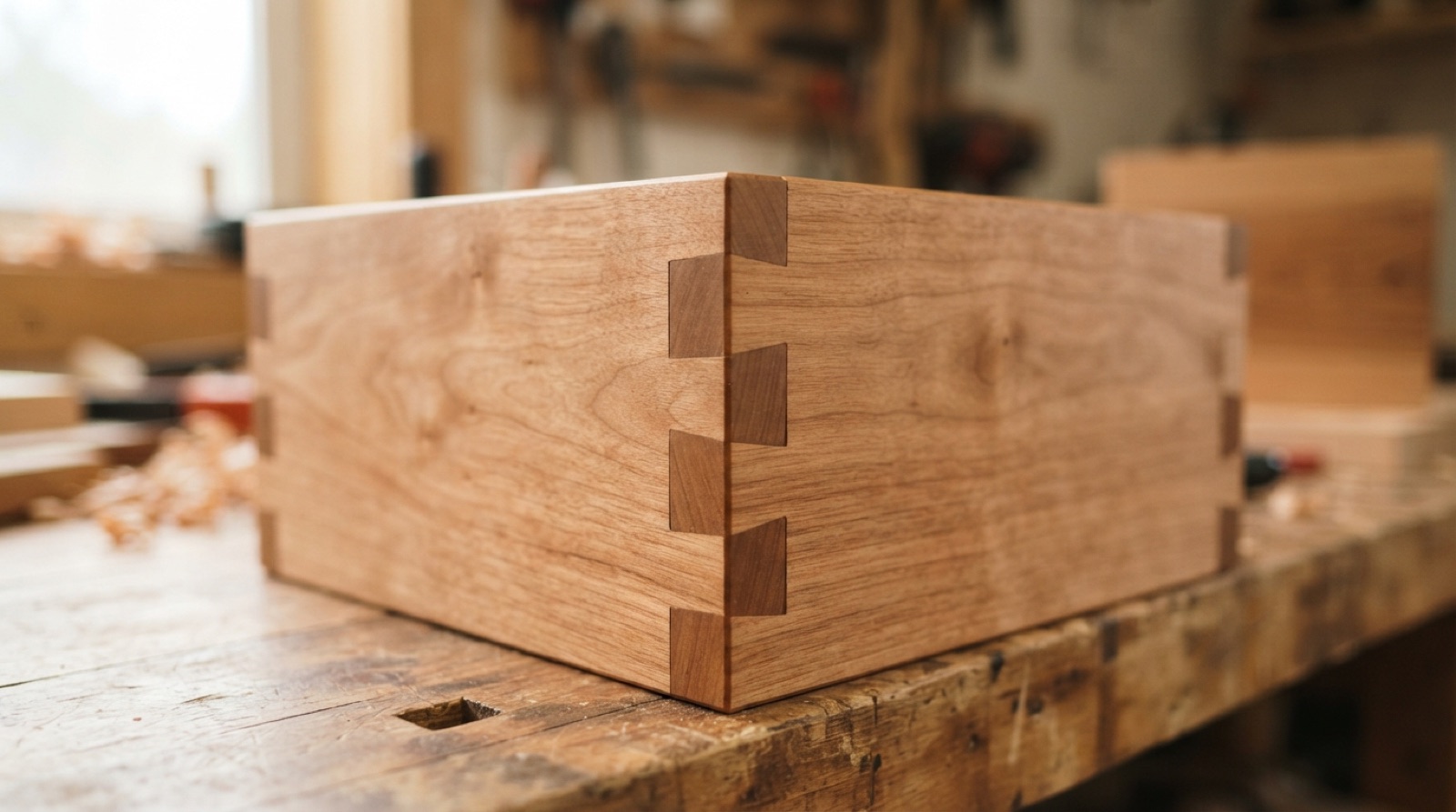
Finger joint, also called a comb joint. Tabs alternate along an edge like interlocking fingers, usually at the corner of a box. A wood shop cuts them on a table saw with a jig. On the laser they are a row of rectangles in your sketch.
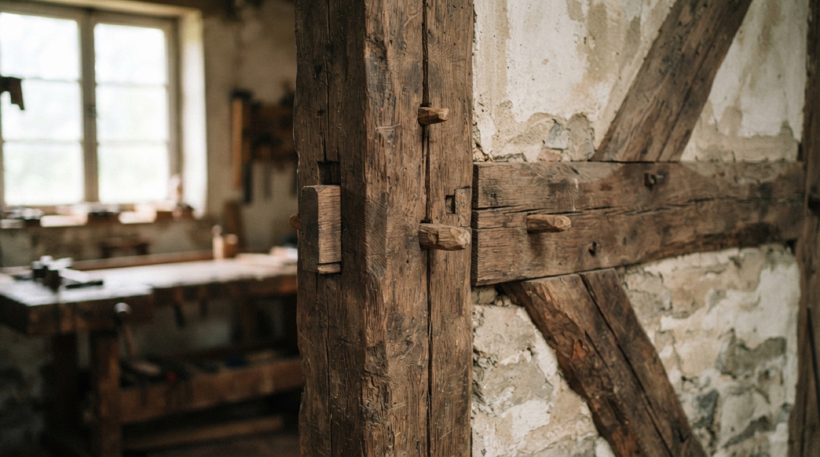
Mortise and tenon, the older cabinetmaking pair. The mortise is the hole, the tenon is the tongue that fills it. When the tenon carries on through and shows on the far side it is called a through tenon, which is what a tab on one laser-cut part does when it pokes out of a slot in another. Timber framers lock theirs with a peg or a wedge. On 3 mm plywood, friction does that job, which is why kerf decides whether the joint works.
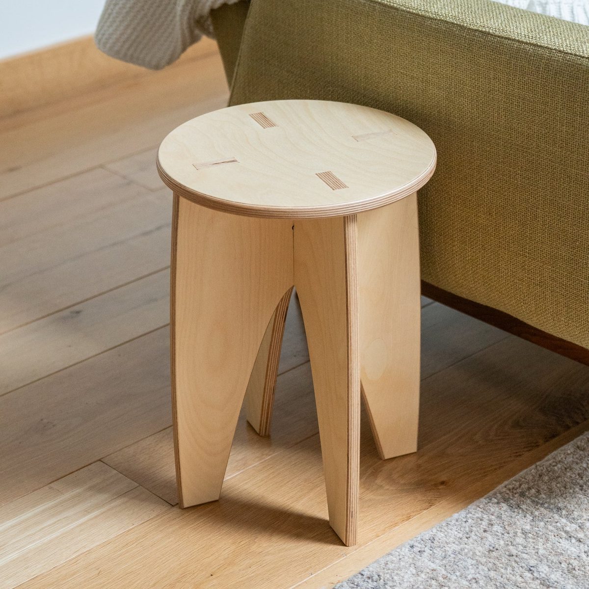
Flat-pack, or interlocking design. The general terms for a three-dimensional object built from nothing but flat sheet. Every part lies in one plane and comes off one sheet, and the assembly is what makes the object 3D. It is how a 2D machine ends up producing objects.
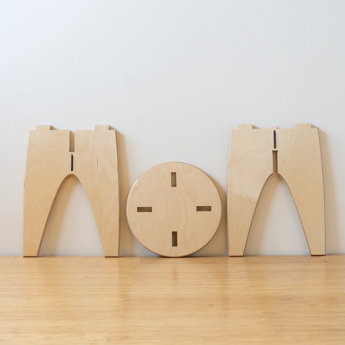
Nothing leaning against that wall is a stool yet. Cross the leg panels on their slots, drop the seat onto the tabs, and the three pieces hold each other square.