 learndesign
Hand-launched glider
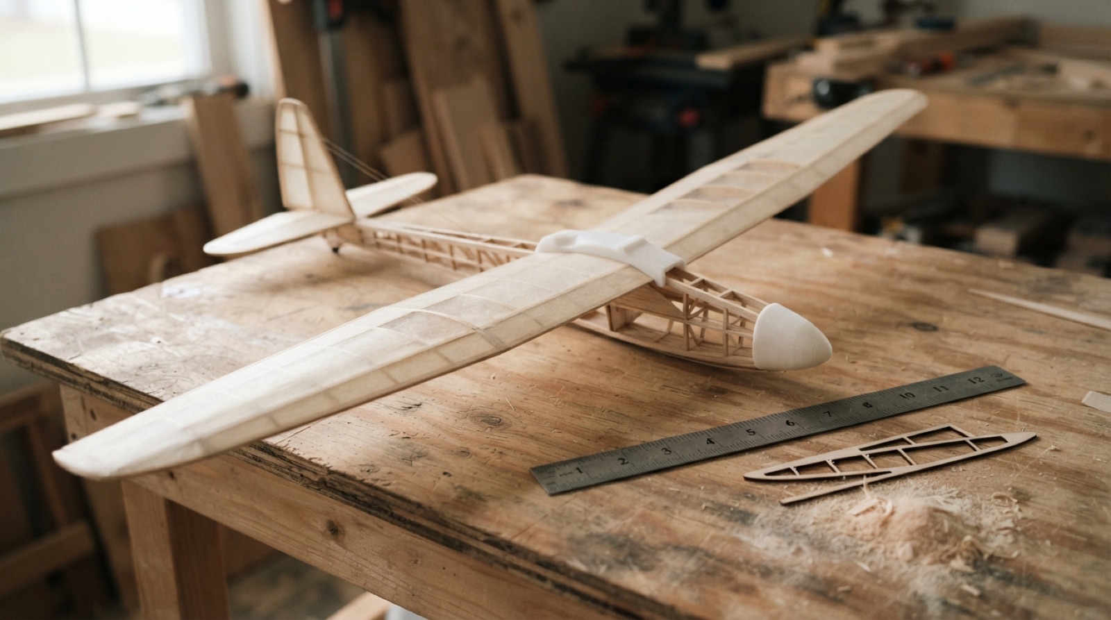
Design a glider that flies straight and far from a hand launch. Airfoil ribs and a fuselage from laser-cut balsa, a printed nose and wing saddle, and a test log that proves the glide ratio got better.
Overview
A glider has no engine, so it trades height for distance and nothing else. The wing decides how good the trade is. A long, thin wing with a cambered airfoil goes further than a short, fat, flat one, and a glider with its balance point in the right place goes further than one that porpoises or dives. You are chasing one number: glide ratio, distance forward divided by height lost, from a hand launch off the top of the bleachers or a stepladder.
The build is a balsa wing with laser-cut ribs on a strip spar, a balsa fuselage, a printed nose that carries the ballast, and a printed saddle that lets you move the wing fore and aft to find the balance point. The tail is flat balsa. Nothing about the structure is new; what is new is that every part comes out of a Fusion model where span and chord are parameters, so a second wing with a different aspect ratio is an afternoon, not a week.
Fifteen launches minimum, logged. The first five will be bad. The log is where the design happens: move the wing, add a washer, bend the elevator, launch again, write it down. A glider that flies 12 m from 2 m up has a glide ratio of 6. A good one from this project gets to 10.
Skills needed
- How a wing makes lift↗Angle of attack, camber, and why a flat plate flies but a curved one flies better. Enough to make a decision, not a lecture.
- Stabilityresource comingCentre of gravity ahead of the centre of lift, dihedral for roll, a tail big enough to hold the nose where you put it. Get these three right and the glider flies itself.
- Glide ratioresource comingDistance forward divided by height lost. It is the one number this project chases, and it is easy to measure.
- Airfoil ribs in FusionImport a section from airfoiltools.com, scale it to your chord, offset it for the spar and the covering, and pattern the ribs along the span.
- Laser-cut balsaBalsa cuts at low power, fast. Test on scrap first; a scorched rib is a weak rib.
- Printing light partsA nose, a wing saddle and a tail mount, printed hollow or in 10% infill. Every gram at the tail costs three at the nose.
Assessment
| Criterion | Developing | Proficient | Exemplary |
|---|---|---|---|
| Design brief | A picture of a glider | Three views with span, chord and area worked out, and a CG estimate | Choices explained against lift, stability and mass, with a number for each |
| Fusion model | Parts drawn separately, not to size | One assembly; ribs patterned from a real airfoil; span and chord as parameters; DXF and STL exported from it | Changing span regenerates the ribs, spar and covering pattern with nothing to fix |
| Build quality | Warped wing, heavy glue joints, tail not square | Wing straight, ribs aligned, tail square to the fuselage, covering tight | Under 35 g with no compromise on stiffness |
| Flight log | A few distances | Fifteen launches, each with height, distance, and the one thing changed | Glide ratio plotted against changes; the log shows the improvement |
| Glide ratio | Below 5 | 5 to 8 | Above 8, repeatable across three launches |
| Reflection | What happened | The two changes that mattered most and why, in terms of lift, drag or balance | A next design proposed from the data, with numbers |
Build quality and the flight log are weighted highest. A glider that is not straight cannot be tuned, and a glider that is not logged was not designed.
Deliverables
- A one-page design brief with a three-view sketch, target span, chord, wing area and the estimated centre of gravity
- A Fusion model of the glider with ribs, spar, fuselage, tail and printed parts, span and chord as parameters
- The flying glider, covered and balanced
- A flight log of at least fifteen launches over three sessions, each with distance, height and what changed
- A final glide ratio with the two best changes you made and why they worked
Materials
- Balsa sheet 1.5 mm and 3 mm, 100 × 900 mm, one of each per student
- Balsa strip 3 × 3 mm for spars and longerons, two lengths
- PLA for the nose, saddle and tail mount
- Tissue paper or 1 mm foam sheet for wing covering, PVA glue, CA glue for the tail
- Modelling clay or steel washers for ballast
Steps
Week 1: Design the wing
- Watch the lift video. Then hold a sheet of paper flat in a fan’s stream, and then curved. Write down what you saw.
- Pick an airfoil from airfoiltools.com. A thin, low-camber section like the AG03 or a flat-bottom Clark Y both work at this size. Download the coordinates.
- Fill in the brief: span, root and tip chord, wing area, tail sizes and the CG position from the starting numbers. Sketch a three-view.
- In Fusion, import the airfoil as a sketch, scale it to the root chord, and cut a notch for the 3 × 3 mm spar at the thickest point. Make span and chord parameters. Pattern the rib along the span, scaling toward the tip.
- Model the fuselage as a 3 mm balsa profile, the nose as a printed shell with a cavity for ballast, and the saddle as a printed part that clamps the wing and slides 20 mm fore and aft on the fuselage.
Week 2: Build
- Export ribs, fuselage and tail as DXF. Cut a single test rib on scrap balsa and find the power that cuts clean without scorching. Then cut the set.
- Print the nose, saddle and tail mount at 10% infill, 0.16 mm layers. Weigh them. If the nose is over 8 g, print it again with thinner walls.
- Build the wing flat on a board over the printed plan. Pin the spar, glue each rib square to it, and let it dry before you lift it. Set the dihedral by gluing the two halves with a 25 mm block under each tip.
- Cover the wing with tissue and thinned PVA, or 1 mm foam and glue stick. Pull it tight. A wrinkled covering is drag you can see.
- Glue the tail on square. Sight down the fuselage from the back: the stabiliser must be parallel to the wing and the fin must be vertical. Fix it now; you cannot fix it later.
Week 3: Fly, log, improve
- First launches at head height across the gym, gently, nose slightly down. Watch what it does and write it down before you touch anything.
- Fix the flight one thing at a time. Dives: move the wing forward or take out clay. Stalls: the reverse. Turns: check the wing and tail are square before you bend anything, then a small bend of the rudder.
- Once it flies straight, launch from a measured height, 2 m off the bleachers, and measure distance to the touchdown point. Five launches, log each one, take the best three.
- Make a change you think will help, the wing position, the ballast, a slight up-bend on the elevator, and do five more. Log them.
- Final session: best three of five from the same height. That is your glide ratio. Write the reflection from the log.
Stretch options
- Cut a second wing with a span of 800 mm from the same Fusion file and compare the glide ratio. Explain the difference with aspect ratio.
- Add a printed catapult hook and launch with an elastic band from a fixed peg. Compare distances; the launch speed is now the same every time.
- Fit a 1 g flight recorder (a small accelerometer logger) in the nose and read the flight profile.