 learndesign
A 3D-printed model rocket
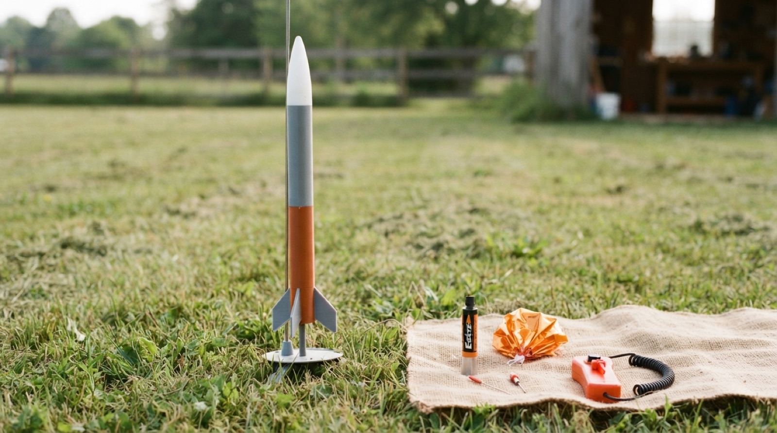
Design, simulate, print and fly a rocket on a commercial 18 mm model rocket motor. Stability comes from the numbers before it comes from the launch pad. Recovery has to work, the flight has to be safe, and the altitude has to be measured.
Overview
A model rocket on a small commercial motor climbs a hundred to three hundred metres in a couple of seconds, pops a parachute at the top, and comes back. Whether it climbs straight or corkscrews into the ground is decided before launch by two points on the drawing: the centre of gravity and the centre of pressure. If gravity leads pressure by at least one body diameter, the air pushes the rocket back onto its line every time it wanders. If not, it flips. Everything else about the design serves that margin and the recovery.
Printing the rocket means the shape is entirely yours. Nose cone profile, body diameter, fin count and shape, how the parts split and join. It also means you have to design around the printer: thin fins that stay stiff, a body that is light enough to fly on a small motor, a motor mount that survives the heat and the thrust, and an ejection charge that has to blow the nose off without melting the airframe.
Design it in OpenRocket first, print it second, fly it third. Then compare what the simulation said to what the altitude measurement says, and change something.
Skills needed
- How a rocket stays pointed the right wayCentre of gravity ahead of centre of pressure by at least one body diameter. Fins move the pressure centre back; nose weight moves gravity forward. Both are yours to set.
- Simulating the flight↗OpenRocket takes the geometry and the motor and gives stability margin, apogee, speed off the rod and descent rate. Design in it before printing anything.
- Modelling for printThe nose cone by revolve, the body as a tube, fins as thin plates with a root that locks in. Split for the bed, oriented for strength along the airflow.
- Designing for the motor and the ejection chargeA motor mount that holds an 18 mm motor and takes the thrust; an engine block so it cannot go forward; a heat-tolerant path for the ejection gas; clearance for wadding.
- RecoveryA parachute or a streamer sized for the mass, a shock cord anchored so it does not pull through, a descent rate that lands the rocket in one piece.
- Safe launching↗Electrical ignition from at least 5 m, a launch rod, a field big enough for the expected altitude, wind limits, a countdown, and the range rules everyone follows.
Assessment
| Criterion | Developing | Proficient | Exemplary |
|---|---|---|---|
| Design sheet | Numbers missing or guessed | Every number from the simulation; margin, mass, apogee and rod speed within constraints | Design choices justified against the numbers; two configurations compared |
| Simulation | Rocket drawn, not simulated | OpenRocket model matches the print; motor loaded; margin checked | Simulation used to choose fin size and nose weight, and updated after flight |
| Print design | Heavy, fragile fins, motor loose | Light, fins stiff and aligned, motor mount takes thrust and heat, parts fit | Airframe engineered for mass: hollow where it can be, solid where it must be |
| Recovery | Chute too small or tangled; cord tears out | Sized for the mass, packed properly, deploys | Reliable across flights; damage-free landings |
| Safe launching | Rules skipped | Checklist completed, rules followed, range procedure run | Runs the range for others; catches a problem before launch |
| Flight record | One flight, no measurement | Two flights, altitude measured, compared to prediction | Difference explained and a design change tested on a third flight |
Deliverables
- A design sheet with mass, length, diameter, fin geometry, motor choice, stability margin, predicted apogee and predicted speed off the rod
- The OpenRocket file and the Fusion model, with fin span, nose length and body length as parameters
- The printed rocket, assembled, with the motor mount, engine block, recovery system and a launch lug
- A pre-flight checklist, completed and signed for each flight
- A flight record: at least two flights, with observed altitude, recovery result, damage and the wind
- A comparison of predicted and measured altitude, and one design change made from it
Materials
- PETG or ASA for the airframe and fins (PLA softens near the motor); a printed or cardboard body tube
- 18 mm model rocket motors, A8-3 for first flights, B6-4 or C6-5 once the rocket is proven; igniters and plugs
- Recovery wadding, a plastic or nylon parachute or a mylar streamer, elastic shock cord, a swivel, a printed or wooden nose weight
- A launch pad with a 3 mm or 5 mm rod, a launch controller with a safety key and at least 5 m of wire, a blast deflector
- A phone or a simple altimeter, and an angle-measuring stick or app to measure altitude from a known distance
- Nose weight: clay, washers or a printed cavity for coins; epoxy for the motor mount
Steps
Week 1: Design in the simulator
- Learn the parts: nose cone, body, fins, motor mount, engine block, launch lug, shock cord, recovery. Look at a commercial kit if one is around.
- Build the rocket in OpenRocket: body diameter 30 to 40 mm, length 300 to 450 mm, three or four fins, an 18 mm motor mount. Load an A8-3.
- Read the results: stability margin, apogee, speed off the rod, descent rate. Adjust fin span, fin position and nose weight until every number sits in the constraints. Write down what each change did.
- Choose the nose profile (ogive or conical) and the fin shape. Fins swept back and mounted at the very tail move the pressure centre back and help margin.
- Fill in the design sheet.
Week 2: Model and print
- Model in Fusion from the OpenRocket dimensions with body length, diameter, fin span and nose length as parameters. Nose cone by revolve, with a shoulder that fits the body with 0.2 mm clearance and a loop for the shock cord.
- Model the motor mount: a tube for the motor with an engine block ring at the top and a hook or friction fit; centring rings to the body; a gap above for wadding and the chute.
- Model the fins as 1.5 to 2 mm plates with a tab that slots through the body into the motor tube, so thrust and landing loads go into the structure. Add a launch lug.
- Slice: body vertical, thin walls, no infill; fins flat on the bed for strength across the span; nose vertical, with a cavity for weight. PETG or ASA everywhere near the motor. Print.
- Assemble with epoxy at the motor mount and fins. Check fin alignment by sighting down the body. Weigh it, with a motor, and mark the actual centre of gravity by balancing.
Week 3: Recovery and preflight
- Size the parachute for the actual mass using the simulator’s descent rate. Cut it, attach shroud lines, fit a swivel. Anchor the shock cord to the body with a printed or glued mount, then test it with a hard pull.
- Pack it: wadding above the motor mount, then the chute rolled with lines outside, then the cord, then the nose. It must slide out with a gentle tug.
- Write the pre-flight checklist: motor, igniter, plug, wadding, chute packed, nose fit, lug on rod, launch angle, wind, range clear, controller armed last.
- Do a ground ejection test if a motor and a safe space are available: it proves the nose leaves and the chute clears.
- Measure the field. Work out where the rocket will land in the day’s wind at the predicted altitude. If that is off the field, do not fly.
Week 4: Fly, measure, revise
- Fly on the A8-3 first. Two people measure altitude from a known baseline with an angle-measuring stick, or an altimeter rides along. Record the wind.
- Observe: straight, weathercocked, spun, tumbled. Recovery: deployed, tangled, late. Damage on landing. Photograph.
- Compare measured altitude to predicted. Work out why they differ: mass, drag from the print surface, fin alignment, wind.
- Make one change from the data. A smoother nose, lighter body, bigger fins, better packing. Fly again, on the same motor, and then on a B if the first flights were clean.
- Complete the flight record and the comparison. Say what the next rocket would be.
Stretch options
- Design for a C6-5 from the start and measure how much the extra altitude costs in field size and recovery.
- Add a payload bay for an altimeter and log the whole flight.
- Design the fins for minimum drag: airfoil the leading edge, and compare altitude to flat plates.
- Two-stage on 18 mm motors, once the single-stage rocket has three clean flights.