 learndesign
Measuring with calipers
Calipers measure three ways, across a part with the big jaws, inside a hole with the small jaws, and down into a hole with the rod on the end. How to hold them for each, what the number means, and how to write it down so you can model from it.
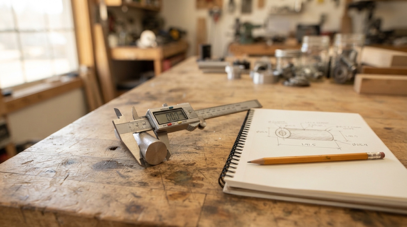
Calipers turn a part into numbers. A ruler gets you to the nearest half millimetre if you squint. Calipers get you to a hundredth, and they do it three different ways from the same tool: across the outside of a part, across the inside of a hole, and down into a hole from the surface. Every replacement part, every press fit and every teardown table starts here.
The parts of a caliper
The big jaws at the bottom measure outside dimensions. The small knife-edged jaws on top measure inside. The thin rod that slides out of the end of the beam measures depth. All three move together, so whatever the display says is true for all three at once. The thumb wheel slides the jaw; the lock screw holds it so you can lift the caliper off the part and read it.
Before you measure
- Close the jaws all the way and press zero. If it does not read 0.00, there is dirt or a chip between the jaws. Wipe them and try again.
- Check the units. The mm/in button switches them, and a caliper left in inches will put a 0.5 in your table where you expected 12.7.
- Hold the caliper by the beam and slider, and use the thumb wheel to move the jaw. Do not push the jaws onto the part with your other hand.
Outside: across a part
Open the jaws wider than the part, put the part deep in the jaws, near the beam rather than out at the tips, and close them until they just touch. The jaws should be square to the part, not tilted. Tighten with the thumb wheel until the caliper stops, then stop. Squeezing harder bends the jaws and gives a smaller number, and on a 3D print it dents the plastic.
On a round bar, rotate the bar a quarter turn and measure again. If the two numbers differ, the bar is not round, and you should write down both.
Inside: a hole or a slot
Put the small jaws into the hole closed, then open them until both tips touch the wall. The tips are the only part that measure, so push the jaws in far enough that the flat faces are against the wall, not the rounded corners. Rock the caliper gently. For a round hole, you want the largest reading, because that is the diameter; anything smaller is a chord. For a slot, you want the smallest reading across it, because that is the true width.
Inside jaws are thin and short. In a deep hole they measure the opening, not the bottom. If the hole tapers, a draft angle in a moulded part for example, measure at the top and note that it is the top.
Depth: how deep a hole or a step is
Stand the caliper on its end with the flat end of the beam on the surface, then slide the rod down until it touches the bottom. Keep the beam vertical. If it leans, the rod reaches the bottom on an angle and reads long. The rod is thin and only touches one point, so for a wide hole with a rough bottom take two or three readings and use the smallest.
The same move measures a step: beam end on the high surface, rod down to the low one.
Reading the number
A digital caliper shows two decimal places. The last digit is not as trustworthy as it looks. A good caliper is accurate to about 0.02 mm; a cheap one, held by a student, is doing well at 0.05 mm. Read 12.68 and 12.72 on the same bar as “12.7”. Write down what the display says, but model with the rounded number, and do not design a fit that depends on the second decimal.
Dial calipers work the same way with a needle instead of a display: the beam scale gives millimetres and the dial gives the fraction. Vernier calipers have no moving parts to fail and are worth learning, but the digital ones on the bench are what you will use most days.
Mistakes that show up in the number
- Measuring at the tips. The outside jaws are strongest at the beam. A part held at the tips can lever them apart and read big.
- Tilting. Any angle between the jaws and the part adds length. Look straight down at the jaws and the part before you read.
- Measuring over a thread. Calipers on a screw read the outside of the thread, which is slightly under the nominal size. See Fasteners, explained for what to do with that number.
- Trusting one reading. Measure twice, in two places. On a printed part, the two numbers tell you how far off your printer is.
- Forgetting the zero. Two people, two calipers, the same part and a 0.2 mm disagreement usually means one of them did not zero.
- Dents. PLA, foam and soft wood compress under the jaws. Close until you feel contact, no further.
Writing it down
A number without a place is useless an hour later. Sketch the part first, by hand, then measure and write each number onto the sketch where it belongs. For anything with more than five or six dimensions, use a table:
| Feature | What was measured | Reading 1 | Reading 2 | Use |
|---|---|---|---|---|
| Body | Outside, across | 24.98 | 25.02 | 25 |
| Bore | Inside, diameter | 8.05 | 8.03 | 8 |
| Bore | Depth from top face | 15.21 | 15.19 | 15.2 |
| Boss | Outside, across | 11.97 | 11.98 | 12 |
Label holes and shafts as what they are. A hole that measures 8.03 was designed as 8 with clearance; a pin that measures 7.97 was designed as 8 with a fit. When you model the part, use the round number and add the clearance yourself. Designing for FDM has the numbers for printed fits.
From numbers to a sketch
In Fusion, every number in your table becomes a dimension on a sketch or a distance in an extrude. Draw the outline from the outside measurements, cut the holes from the inside ones, and set hole and pocket depths from the depth readings. Modelling from sketches covers the workflow, and Fasteners, explained covers the case where the thing you measured has a thread on it.