 learndesign
Pumpkin launcher
Design a machine that throws a payload as far and as repeatably as you can. Prove the mechanism at desk scale with a ping-pong ball, then build it full size from 2×4s and launch a pie pumpkin across the field.
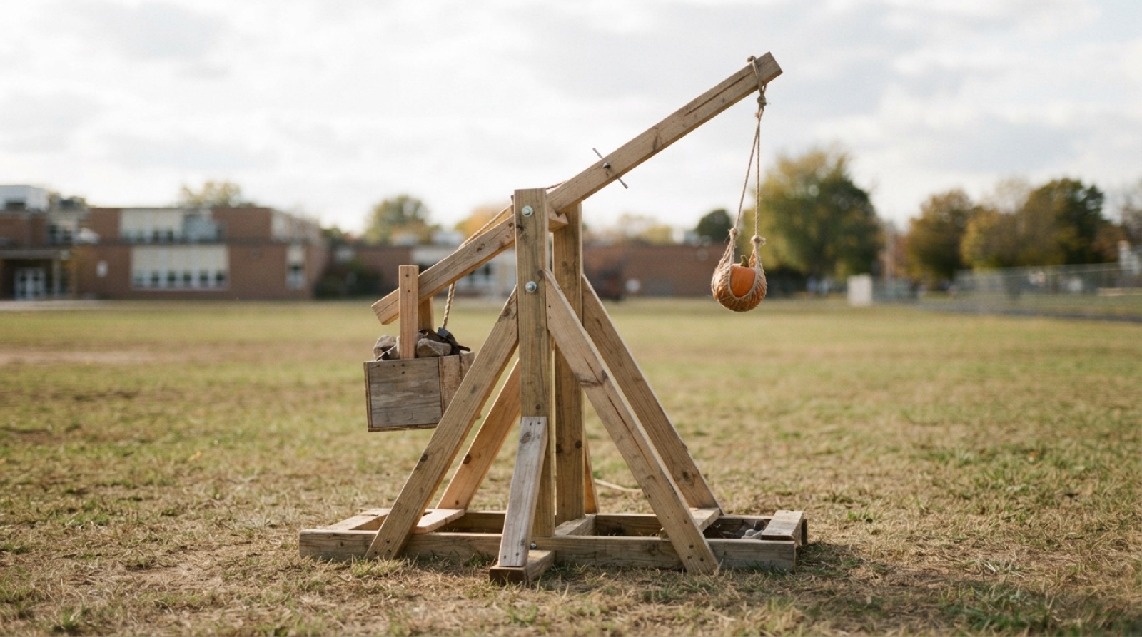
Overview
A launcher is a machine that stores energy slowly and gives it all back at once. That is the whole problem. How you store it, how you hand it to the payload, and when you let the payload go decide how far it flies. The shape of the machine follows from those three decisions, and the woodworking follows from the shape.
You work in a team of three and build twice. The first build is a 1:10 model, laser-cut from 3 mm plywood with printed pivots, that throws a ping-pong ball across the room. It is cheap and quick, so you can change the arm ratio or the release angle and test again the same lesson. The second build is the same machine at full size, from 2×4s, throwing a pie pumpkin on the field. Both come from one Fusion model with a scale parameter, so what you learn at desk scale carries straight into the cut list.
Any mechanism is allowed: trebuchet, torsion catapult, spring catapult, elastic slingshot, or something of your own. What is not allowed is compressed gas or anything that stores energy in a way you cannot see and let down by hand. Range counts, but consistency counts more. A machine that puts three pumpkins within 5 m of each other beats one long throw and two that go sideways.
Skills needed
- Projectile motion↗Range depends on launch speed and angle. 45° is only best when the release height is the landing height and there is no drag. Play with the simulation before you decide anything.
- Energy storage and releaseCounterweight, torsion, spring or elastic. Each stores energy differently and gives it back differently. Know the trade before you pick.
- Levers and mechanical advantageArm ratio, pivot height and where the payload lets go set the launch speed. Small changes here beat a bigger counterweight.
- Scale modelling in FusionOne parametric model. Print or laser-cut it at 1:10, then change the scale parameter and print the full-size cut list from the same file.
- Laser cutting and 3D printing a working modelPivots need clearance, not interference. Print axles and bushings; cut frames from 3 mm plywood.
- Framing with 2×4sButt joints, half-laps and carriage bolts. Triangulate anything that must not rack.
- Trigger designThe trigger holds the full stored energy and lets it go on command, from a distance. This is the part that gets designed most carefully and tested first.
Assessment
| Criterion | Developing | Proficient | Exemplary |
|---|---|---|---|
| Mechanism research | One type described, no comparison | Three types compared on energy source, complexity and safety; choice justified | Comparison uses numbers: stored energy, arm ratio, expected launch speed |
| Fusion model | Drawn at one size, dimensions typed in | Parametric; scale, arm lengths and release angle drive the model; cut list produced from it | A parameter change updates every part and the drawing; used to test ideas before cutting |
| Desk model and test log | Fires, but no record | Ten logged launches, at least one variable changed and its effect measured | A clear finding from the log that changed the full-size design |
| Full-size build | Racks under load, joints loose | Square, triangulated, bolted at the pivot, passes the drop test first time | Built like it will last a season; nothing flexes that should not |
| Trigger and safety | Released by hand at the machine | Cord release from 3 m, holds full load, releases every time | Reset, load and fire in under two minutes, from behind the line |
| Launch record | Distances only | Distances with settings for each launch and a reflection naming the limiting factor | The limit was tested: a setting was changed on the field and the effect recorded |
The full-size build and the trigger are weighted highest. A launcher that is not safe is not finished.
Deliverables
- A one-page mechanism comparison covering at least three launcher types, with a sketch and the energy source of each, and your choice justified
- A parametric Fusion model of your launcher with the scale, arm lengths, counterweight mass and release angle as parameters
- The 1:10 working model, laser-cut and printed, with a test log of ten ping-pong ball launches
- The full-size launcher, safety-checked, with a trigger that fires from 3 m away
- A launch record for the full-size machine with distances, the settings for each launch, and a reflection on what limited the range
Materials
- 3 mm plywood, 300 × 300 mm, and PLA for the desk model
- Six 2×4 × 8 ft spruce, per team of three
- Carriage bolts M10 × 120 mm with nuts and washers, deck screws 3 in and 2½ in
- Paracord, 1 m of nylon strap for the sling, a bucket or sandbags for counterweight
- Ping-pong balls for the model, pie pumpkins (1 to 2 kg) for the field
Steps
Week 1: Choose a mechanism
- Watch a trebuchet, a torsion catapult (an onager) and a spring or elastic launcher fire. For each, write down where the energy is stored, how it reaches the payload, and what decides the release moment.
- Compare them on a page: sketch, energy source, number of parts, what fails first, how hard it is to make consistent. Pick one and say why.
- Run the projectile simulation. Find the launch speed you would need to throw 1 kg 30 m. Work backwards: how much stored energy is that, and what counterweight or spring gives it to you?
- Sketch your machine at 1:10, side and front. Mark the pivot, the arm ratio, and the tie-down points.
Week 2: Model it and prove it small
- New Fusion design. First parameter is
scale. Every length is written as a multiple of it, soarm_long = 2000 mm * scale. Addarm_short,pivot_height,counterweight_mass,release_angle. - Model the frame as flat parts that slot together, because that is what the laser cuts and what 2×4s do at full size. Model pivots as a printed bushing and axle with 0.3 mm clearance.
- Set
scale = 0.1. Export the frame parts as DXF and the pivots as STL. Cut and print. Assemble with glue and a little masking tape. - Launch a ping-pong ball ten times. Record the distance and the settings each time. Change one thing, the release angle or the arm ratio, and do five more. Write down what happened.
Week 3: Build it full size
- Set
scale = 1. Check every part against the 2×4 you actually have: 38 × 89 mm, not 2 in × 4 in. Adjust the joints. Print the cut list and a drawing of each subassembly. - Cut the frame. Two people cut, one checks each piece against the list before it goes in the pile. Label everything.
- Assemble the base first, then the A-frames, then the crossbar with the pivot. Triangulate as you go. Check square with a diagonal measurement, not by eye.
- Fit the arm and the pivot with a carriage bolt and washers, not screws. Swing it by hand with nothing attached; it should move freely with no side play.
- Build the trigger. Test it holding the full counterweight with the arm cocked, released by cord from 3 m, ten times in a row, before anything is loaded in the sling.
Week 4: Launch day
- Stake or tie down the machine. Run the tape line. Drop test with no payload. Fix anything that moves.
- Three launches with a water balloon first, to find the release setting. Then three with a pumpkin. Measure every distance from the same point at the base.
- Between launches, change one setting only, and write it down before you fire.
- Reflection: what limited your range, arm speed, release timing, drag or the frame flexing, and what you would change first with one more week.
Stretch options
- Fit a phone in a printed mount on the crossbar and film the release at 240 fps. Measure the launch angle and speed from the video and compare it to the simulation.
- Model the arm as a beam in Fusion’s simulation workspace and find the load at which it breaks. Then decide if the counterweight can go up.
- Build a photogate or an accelerometer logger on an Arduino and record the arm’s swing.